Refrigerant Transfer Pumps & Relevant Accessories
Refrigerant Transfer Pumps
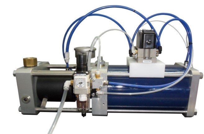
RTP 6310 RTP 6315
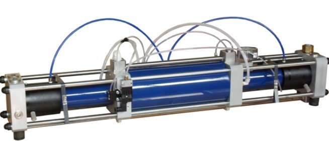
RTP 6325T
RTP 6310 : 3.6 l/min Refrigerant transfer rate up to 40 bar
RTP 6315 : 6.0 l/min Refrigerant transfer rate up to 40 bar
RTP 6325T : 13.0 l/min Refrigerant transfer rate up to 40 bar
RTP - Devices to pressurize and transfer refrigerant to delivery lines
The pumps designed specifically for the transfer and pressurization of refrigerants are provided with a complete equipment in adjunct, which includes:
Complementary Tools
RTP 6315 : 6.0 l/min Refrigerant transfer rate up to 40 bar
RTP 6325T : 13.0 l/min Refrigerant transfer rate up to 40 bar
RTP - Devices to pressurize and transfer refrigerant to delivery lines
The pumps designed specifically for the transfer and pressurization of refrigerants are provided with a complete equipment in adjunct, which includes:
- Pressure regulator fluid in the supply line
- Gauge pressure of the fluid in the supply line
- Safety valve by-pass to protect the RTP from possible over-pressure in the discharge line
- Unit filter / dryer for compressed air
Complementary Tools
- Filter on inlet with high capacity, to protect the pump from solid impurities that may be pre- sent the treated refrigerant
- Quick couplings with flat faces for couplings having the suction and discharge, to enable rapid connections and disconnections from the refrigerant lines, in case of pump maintenance operations
- Suction hose to connect the filter to the storage tank and to the pump
- Hose in the supply to connect directly the pump to the refrigerant charging unit
- Safety valve for emission of refrigerant to the outside or inside the tank in case of emergency
- Hydro pneumatic accumulator to maintain stable discharge pressure the case of unexpected refrigerant flow variation in the distribution system
- Lubricator compressed air (only necessary in the case of use of lubricated compressed air)
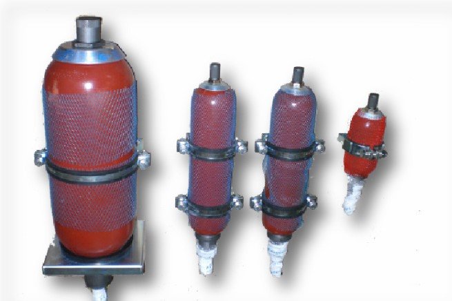
Hydro pneumatic Accumulators
The hydro pneumatic accumulator is a device designed specifically for the storage of liquids under pressure. As liquids are, for all practical purposes, incompressible, the objective is achieved by utilizing the compressibility of gases
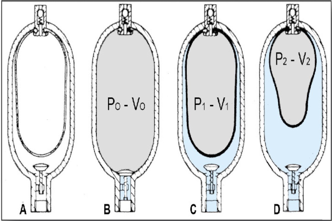
A- A flexible separator bladder is fitted into a pressure vessel (accumulator shell).
B-Through a special valve an inert gas (nitrogen) is introduced into the bladder with pressure PO The bladder expands, filling the entire volume VO of the accumulator shell.
C- When circuit pressure P1 is higher than the gas pre-charge pressure PO, the liquid valve opens, and the bladder is compressed reducing the gas volume to V1.
D- When the liquid pressurizer to P2, the volume of gas reduces to V2 with an attendant rise in pressure, thus balancing the liquid pressure. This means that the accumulator has been pressurized ∆V=V1-V2 and a potential energy has been created to be utilized as desired
The accumulators can be conveniently used in different applications, of which the main ones are :
The accumulators are available for many standards Industrial Refrigerants and fluids as :
- Reserve liquid under pressure, to temporarily maintain high levels of flow rate.
- Stabilizer of pressurized lines, to limit the fluctuations for thermal changes or the flow rate.
- Energy reserve in the form of pressurized fluid or hydraulic spring.
- Absorber hammering or pulsation of the fluid.
The accumulators are available for many standards Industrial Refrigerants and fluids as :
- refrigerants HFC (R134a, R404A, R407C, R410A, R507, others)
- refrigerants HCFC (R22),
- refrigerants CFC (R12, R502),
- refrigerants HC (R600a, R290)
- other “natural gases” as NH3 (R717) e CO2 (R744), industrial oils or general fluids
- CE-PED, ATEX and ML available on request
Powered by
MakeWebEasy.com